5.6 KiB
Creating the hills
To make my plane of grass I first needed a plane. I added a generator function in glutils.cpp which makes a segmented plane for me with as many vertices and faces as specified. This was needed since I plan to add a displacement map capability, but only do so in the vertex shader. I thus need a lot of vertexes. The other route would be to make a texel shader which divides the faces into smaller faces and use it on the plane, which would save memory bandwith. But making it from the start is the easier option.
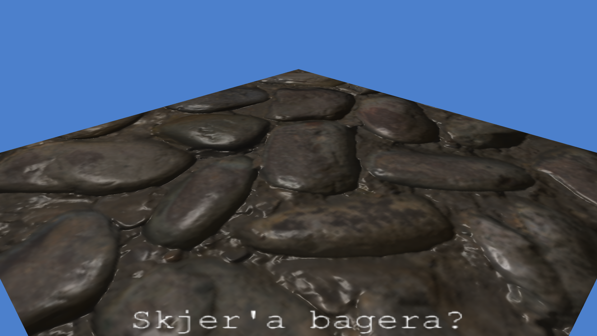
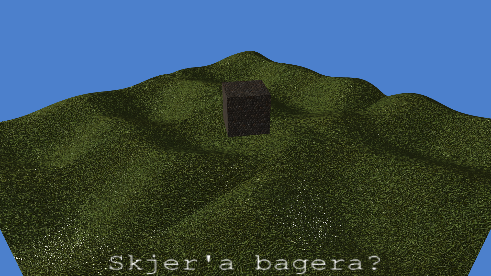
I added the plane to the scene and set the cobble texture on it.
It didn't look right, so I went through the shader again to make sure the lighting was correct. I failed to pass the specular shininess factor properly as a uniform. I also had failed to account for the specular component being negative (before raising it to the power of the shininess). I added this check and now the lighting looks correct.
While at it I added the ability to specify all the color components and the attenuation per light source. With this I'm able to create a sun far away without being bothered by attenuation.
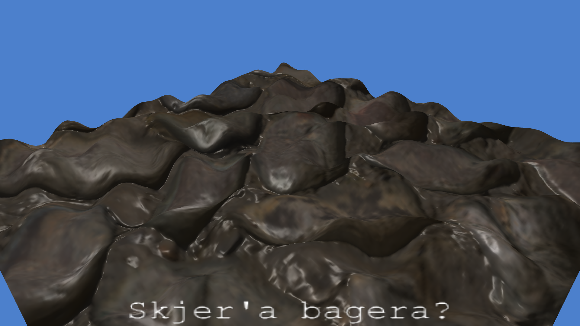
Now for the displacement of the plane. I created a PNGImage generator function which generates a perlin noise texture with the amount of layers and scales specified.
This I registered as the displacement texture for the plane. In the vertex shader I added a isDisplacementMapped uniform shader flag which adds the normal vector multiplied by the displacement to each vertex.
#!/usr/bin/env bash
echo A M A S I N G | boxes -d unicornsay -a c -p h10
I've yet to modify the normals from the displacement, so the hill currently won't cast shadows. I currently don't have a plan on how to fix this. Perhaps use the bitangents to calculate the slope of the displacement in the vertex shader?
At this point I went online a found myself a grass texture and normal map.

#!/usr/bin/env bash
printf "   Something's wrong...!   \n" | cowsay -f head-in | sed -e "s/^/              /"
Apparently, the direction of the normal map colors aren't the same everywhere. I therefore added a flag to the image loader function which will flip the handedness. (inverting the R and G channels).
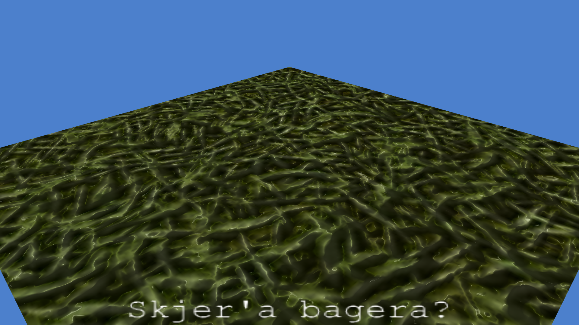
Much better
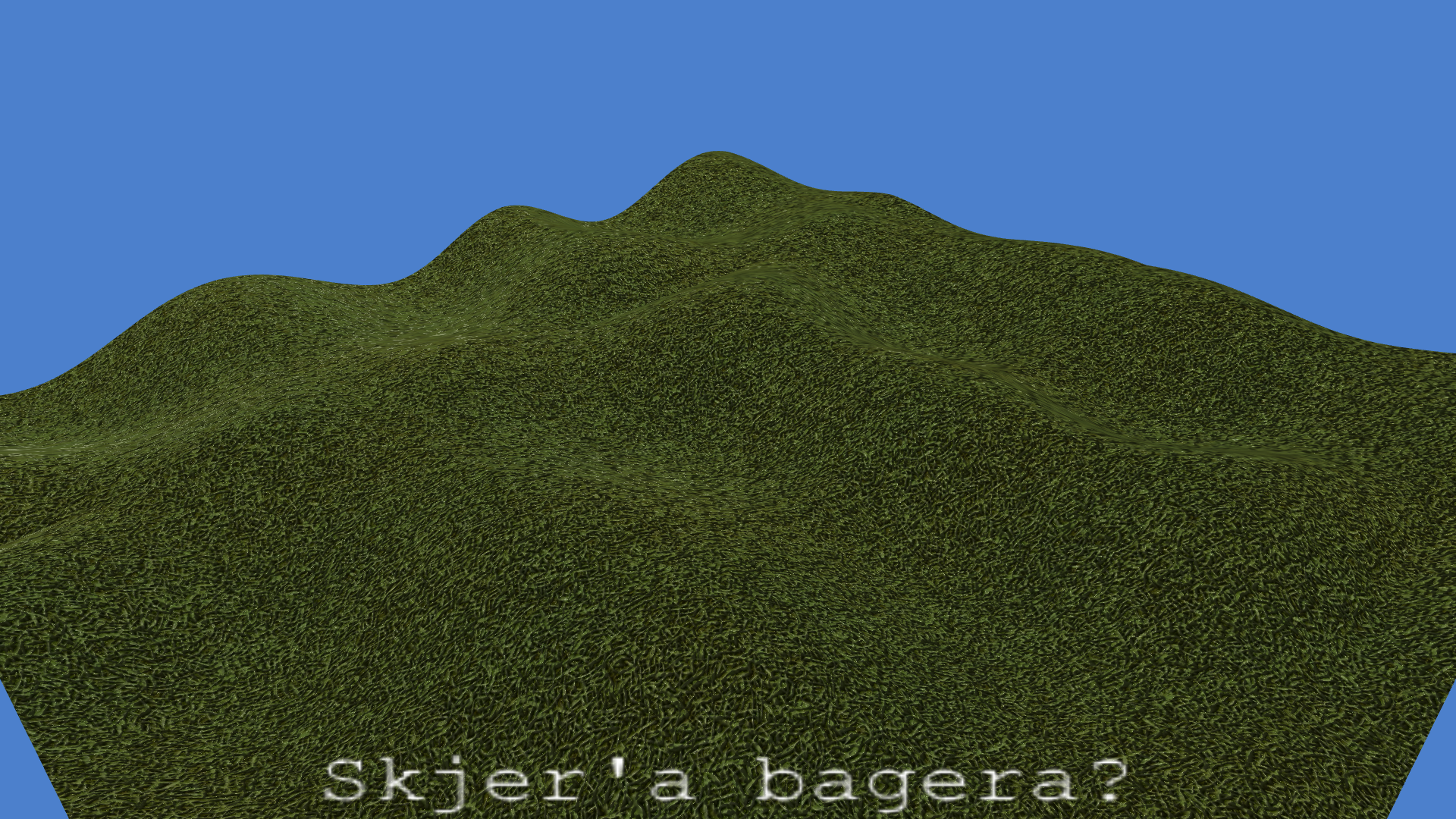
Now we'll up the granularity by decreasing the UV step per vertex along the plane, and enable the displacement map:
Scrolling the field
Now, how can we scroll this plane?
I decided the easies way would be to add a uniform variable called uvOffset to the vertex shader. Now I can simply scroll the plane by adding to this offset to all the UV coordinates in the vertex shader before passing it to the fragment shader:
/*vec2*/plainNode->uvOffset += /*vec2*/speed * timeDelta;
The code above works since I added in some operator overloads for vec2, vec3, and vec4 with scalars.
Now we unfortunately see steep cuts where the perlin noise texture repeats. This we simply fix by mirroring the texture on repeat with GL_MIRRORED_REPEAT:

An another solution to making the perlin noise repeatable is to pass the repeat size into the glm::gtx::perlin function as I create the texture. But as of now I chose the quick and dirty solution. It also has the added effect of creating a less repeating texture. It repeats from 0-2 instead of 0-1.
At this point I was stuck with a bug where the coordinates of the lights were doubled. After two days of debugging I found the line where I update pass the light position into the uniform in the fragment shader:
lights[id].position = vec3(node->MV * vec4(node->position, 1.0));
Which should have been
lights[id].position = vec3(node->MV * vec4(vec3(0.0), 1.0));
...yeah.
Normal mapping the displacement
After that goober, I moved on to try to rotate the normals according the displacement map. After some playing around I landed on this solution in glsl:
\small
if (isDisplacementMapped) {
	float o = texture(displaceTex, UV).r * 2 - 1;
	float u = (texture(displaceTex, UV + vec2(0.0001, 0)).r*2-1 - o) / 0.0004; // magic numbers!
	float v = (texture(displaceTex, UV + vec2(0, 0.0001)).r*2-1 - o) / 0.0004; // magic numbers!
	TBN = mat3(
		normalize(tangent   + normal*u),
		normalize(bitangent + normal*v),
		normalize(cross(tangent + normal*u, bitangent + normal*v))
	);
}
\normalsize
Here I find the slope along the displacement map along the U and V direction. o is the 'origin', and u and v are the tangent and bitangent slope cosines (derived with the help of a few magic numbers which should be made into uniforms really,s ince they only apply for the plane as of now). Using these cosines I can simply add the normal vector multiplied by the cosine to the tangent and the bitangent and normalize them, giving me the new tangents. I can from here derive the new normal vector by simply computing the cross product of the two tangents.
This did however give me a pretty coarse image, so I moved the computation of the TBN matrix from the vertex shader to the fragement shader. This will give me a slight performance penalty, but I can undo the change in a simplified shader should I need the performance boost later. Here we can see how the displacement affects the normals along the displaced plane:
#!/usr/bin/env bash
echo Windows XP background incoming? | boxes -d whirly -a c -p h15